MODULE 1
BASIC STRUCTURE OF DIGITAL COMPUTERS
1.1 Computer types
A computer can be defined as a fast electronic calculating machine that accepts the (data) digitized input information process it as per the list of internally stored instructions and produces the resulting information.
List of instructions are called programs & internal storage is called computer memory.
The different types of computers are:
1. Personal computers: - This is the most common type found in homes, schools, Business offices etc., It is the most common type of desk top computers with processing and storage units along with various input and output devices.
2. Note book computers: - These are compact and portable versions of PC
3. Work stations: - These have high resolution input/output (I/O) graphics capability, but with same dimensions as that of desktop computer. These are used
in engineering applications of interactive design work.
4. Enterprise systems: - These are used for business data processing in medium to large corporations that require much more computing power and storage capacity than work stations. Internet associated with servers have become a dominant worldwide source of all types of information.
5. Super computers: - These are used for large scale numerical calculations required in the applications like weather forecasting etc.,
1.2 Functional unit
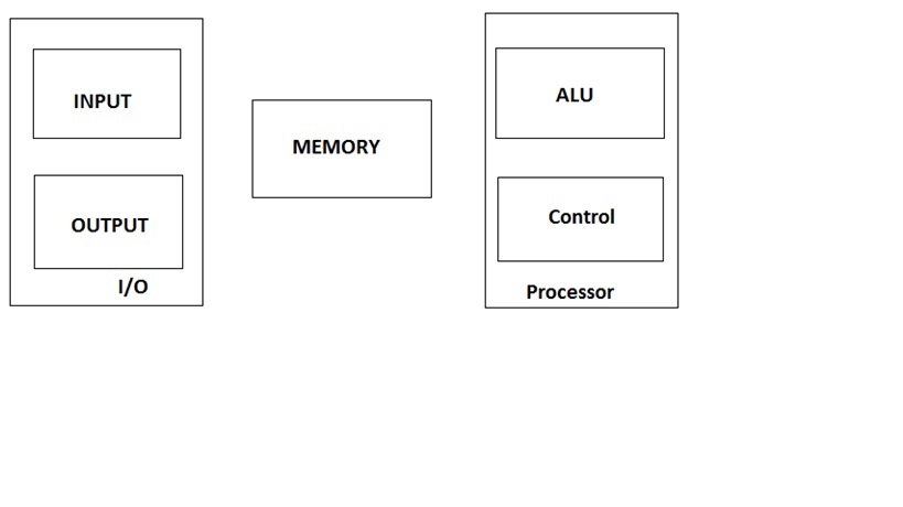
A computer consists of five functionally independent main parts input, memory, arithmetic logic unit (ALU), output and control unit.
 Input device accepts the coded information as source program i.e. high level language. This is either stored in the memory or immediately used by the processor to perform the desired operations. The program stored in the memory determines the processing steps. Basically the computer converts one source program to an object program. i.e. into machine language.Finally the results are sent to the outside world through output device. All of these actions are coordinated by the control unit.
Input unit: -
The source program/high level language program/coded information/simply data is fed to a computer through input devices keyboard is a most common type. Whenever a key is pressed, one corresponding word or number is translated into its equivalent binary code over a cable & fed either to memory or processor.
Joysticks, trackballs, mouse, scanners etc are other input devices.
Memory unit: -
Its function into store programs and data. It is basically to two types
1. Primary memory
2. Secondary memory
1. Primary memory: -
Is the one exclusively associated with the processor and operates at the electronics speeds programs must be stored in this memory while they are being executed. The memory contains a large number of semiconductors storage cells. Each capable of storing one bit of information. These are processed in a group of fixed site
Is the one exclusively associated with the processor and operates at the electronics speeds programs must be stored in this memory while they are being executed. The memory contains a large number of semiconductors storage cells. Each capable of storing one bit of information. These are processed in a group of fixed site
called word.
To provide easy access to a word in memory, a distinct address is associated with each word location. Addresses are numbers that identify memory location. Number of bits in each word is called word length of the computer. Programs must reside in the memory during execution. Instructions and data can be written into the memory or read out under the control of processor.
Memory in which any location can be reached in a short and fixed amount of time after specifying its address is called random-access memory (RAM). The time required to access one word in called memory access time. Memory which is only readable by the user and contents of which can’t be altered is called read only memory (ROM) it contains operating system. Caches are the small fast RAM units, which are coupled with the processor and are Often contained on the same IC chip to achieve high performance. Although primary storage is essential it tends to be expensive.
2 Secondary memory: -
Is used where large amounts of data & programs have to be stored, particularly information that is accessed infrequently.
Is used where large amounts of data & programs have to be stored, particularly information that is accessed infrequently.
Examples: - Magnetic disks & tapes, optical disks (ie CD-ROM’s), floppies etc.,
Arithmetic logic unit (ALU):-
Most of the computer operators are executed in ALU of the processor like addition, subtraction, division, multiplication, etc. the operands are brought into the ALU from memory and stored in high speed storage elements called register. Then according to the instructions the operation is performed in the required sequence. The control and the ALU are may times faster than other devices connected to a computer system. This enables a single processor to control a number of external devices such as key boards, displays, magnetic and optical disks, sensors and other mechanical controllers.
Output unit:-
These actually are the counterparts of input unit. Its basic function is to send the processed results to the outside world.
Examples:- Printer, speakers, monitor etc.
Control unit:-
It effectively is the nerve center that sends signals to other units and senses their states. The actual timing signals that govern the transfer of data between input unit, processor, memory and output unit are generated by the control unit.
1.3 Basic operational concepts
To perform a given task an appropriate program consisting of a list of instructions is stored in the memory. Individual instructions are brought from the memory into the processor, which executes the specified operations. Data to be stored are also stored in
the memory.
Examples: - Add LOCA, R0
This instruction adds the operand at memory location LOCA, to operand in register R0 & places the sum into register. This instruction requires the performance of several steps,
1. First the instruction is fetched from the memory into the processor.
2. The operand at LOCA is fetched and added to the contents of R0
3. Finally the resulting sum is stored in the register R0
The preceding add instruction combines a memory access operation with an ALU Operations. In some other type of computers, these two types of operations are performed by separate instructions for performance reasons.
Load LOCA, R1
Add R1, R0
Transfers between the memory and the processor are started by sending the address of the memory location to be accessed to the memory unit and issuing the appropriate control signals. The data are then transferred to or from the memory.


The fig shows how memory & the processor can be connected. In addition to the ALU & the control circuitry, the processor contains a number of registers used for several
different purposes.
The instruction register (IR):-
Holds the instructions that is currently being executed. Its output is available for the control circuits which generates the timing signals that control the various processing elements in one execution of instruction.
The program counter (PC):-
This is another specialized register that keeps track of execution of a program. It contains the memory address of the next instruction to be fetched and executed.
Besides IR and PC, there are n-general purpose registers R0 through Rn-1
The other two registers which facilitate communication with memory are: -
1. MAR – (Memory Address Register):- It holds the address of the location to be accessed.
2. MDR – (Memory Data Register):- It contains the data to be written into or read out of the address location.
Operating steps are:-
1. Programs reside in the memory & usually get these through the I/P unit.
2. Execution of the program starts when the PC is set to point at the first instruction of the program.
3. Contents of PC are transferred to MAR and a Read Control Signal is sent to the memory.
4. After the time required to access the memory elapses, the address word is read out of the memory and loaded into the MDR.
5. Now contents of MDR are transferred to the IR & now the instruction is ready to be decoded and executed.
6. If the instruction involves an operation by the ALU, it is necessary to obtain the required operands.
7. An operand in the memory is fetched by sending its address to MAR & Initiating a read cycle.
8. When the operand has been read from the memory to the MDR, it is transferred from MDR to the ALU.
9. After one or two such repeated cycles, the ALU can perform the desired operation.
10. If the result of this operation is to be stored in the memory, the result is sent to MDR.
11. Address of location where the result is stored is sent to MAR & a write cycle is initiated.
12. The contents of PC are incremented so that PC points to the next instruction that is to be executed.
The Diversion may change the internal stage of the processor its state must be saved in the memory location before interruption. When the interrupt-routine service is completed the state of the processor is restored so that the interrupted program may completed the state of the processor is restored so that the interrupted program may continue.
1.4 Bus structure
The simplest and most common way of interconnecting various parts of the computer. To achieve a reasonable speed of operation, a computer must be organized so that all its units can handle one full word of data at a given time.A group of lines that serve as a connecting port for several devices is called a bus.
In addition to the lines that carry the data, the bus must have lines for address and control purpose. Simplest way to interconnect is to use the single bus as shown
Since the bus can be used for only one transfer at a time, only two units can
actively use the bus at any given time. Bus control lines are used to arbitrate multiple
requests for use of one bus.
Single bus structure is
- Low cost
- Very flexible for attaching peripheral devices.

All the interconnected devices are not of same speed & time, leads to a bit of a problem. This is solved by using cache registers (ie buffer registers). These buffers are electronic registers of small capacity when compared to the main memory but of comparable speed.
The instructions from the processor at once are loaded into these buffers and then the complete transfer of data at a fast rate will take place.
1.5 Performance
 |
| Fig: Multi bus systems |
1.5 Performance
The most important measure of the performance of a computer is how quickly it can execute programs. The speed with which a computer executes program is affected by the design of its hardware. For best performance, it is necessary to design the compiles, the machine instruction set, and the hardware in a coordinated way.
The total time required to execute the program is elapsed time is a measure of the performance of the entire computer system. It is affected by the speed of the processor, the disk and the printer. The time needed to execute a instruction is called the processor time. Just as the elapsed time for the execution of a program depends on all units in a computer system, the processor time depends on the hardware involved in the execution of individual machine instructions. This hardware comprises the processor and the memory which are usually connected by the bus as shown in the fig c.


Let us examine the flow of program instructions and data between the memory and the processor. At the start of execution, all program instructions and the required data are stored in the main memory. As the execution proceeds, instructions are fetched one by one over the bus into the processor, and a copy is placed in the cache later if the same instruction or data item is needed a second time, it is read directly from the cache.
The processor and relatively small cache memory can be fabricated on a single IC chip. The internal speed of performing the basic steps of instruction processing on chip is very high and is considerably faster than the speed at which the instruction and data can be fetched from the main memory. A program will be executed faster if the movement of instructions and data between the main memory and the processor is minimized, which is achieved by using the cache.
For example:- Suppose a number of instructions are executed repeatedly over a short period of time as happens in a program loop. If these instructions are available in the cache, they can be fetched quickly during the period of repeated use. The same applies to the data that are used repeatedly.
Processor clock: -
Processor circuits are controlled by a timing signal called clock. The clock designer the regular time intervals called clock cycles. To execute a machine instruction the processor divides the action to be performed into a sequence of basic steps that each step can be completed in one clock cycle. The length P of one clock cycle is an important parameter that affects the processor performance.
Memory locations and addresses
Number and character operands, as well as instructions, are stored in the memory of a computer. The memory consists of many millions of storage cells, each of which can store a bit of information having the value 0 or 1. Because a single bit represents a very small amount of information, bits are seldom handled individually.
The usual approach is to deal with them in groups of fixed size. For this purpose, the memory is organized so that a group of n bits can be stored or retrieved in a single, basic operation. Each group of n bits is referred to as a word of information, and n is called the word length. The memory of a computer can be schematically represented as a collection of words. Accessing the memory to store or retrieve a single item of information, either a word or a byte, requires distinct names or addresses for each item location.
It is customary to use numbers from 0 through 2K-1, for some suitable values of k, as the addresses of successive locations in the memory. The 2k addresses constitute the address space of the computer, and the memory can have up to 2k addressable locations.
BYTE ADDRESS ABILITY
We now have three basic information quantities to deal with: the bit, byte and word. A byte is always 8 bits, but the word length typically ranges from 16 to 64 bits. The most practical assignment is to have successive addresses refer to successive byte
This is the assignment used in most modern computers, and is the one we will normally use in this book. The term byte-addressable memory is use for this assignment. Byte locations have addresses 0,1,2, …. Thus, if the word length of the machine is 32 bits, successive words are located at addresses 0,4,8,…., with each word consisting of four bytes.


BIG-ENDIAN AND LITTLE-ENDIAN ASIGNMENTS:-
There are two ways that byte addresses can be assigned across words, as shown in fig. The name big-endian is used when lower byte addresses are used for the more significant bytes (the leftmost bytes) of the word. The name little-endian is used for the opposite ordering, where the lower byte addresses are used for the less significant bytes (the rightmost bytes) of the word.


In the case of a 32-bit word length, natural word boundaries occur at addresses 0, 4, 8, …, as shown in above fig. We say that the word locations have aligned addresses . in general, words are said to be aligned in memory if they begin at a byte address that is a multiple of the number of bytes in a word.
Memory operations
Both program instructions and data operands are stored in the memory. To execute an instruction, the processor control circuits must cause the word (or words) containing the instruction to be transferred from the memory to the processor. Operands and results must also be moved between the memory and the processor.
Thus, two basic operations involving the memory are needed, namely, Load (or Read or Fetch) and Store (or Write). The load operation transfers a copy of the contents of a specific memory location to the processor. The memory contents remain unchanged. To start a Load operation, the processor sends the address of the desired location to the memory and requests that its contents be read. The memory reads the data stored at that address and sends them to the processor.
The store operation transfers an item of information from the processor to a specific memory location, destroying the former contents of that location. The processor sends the address of the desired location to the memory, together with the data to be written into that location. An information item of either one word or one byte can be transferred between the processor and the memory in a single operation. Actually this transfer in between the CPU register & main memory.


Instructions and instruction sequencing
A computer must have instructions capable of performing four types of operations.
• Data transfers between the memory and the processor registers
• Arithmetic and logic operations on data
• Program sequencing and control
• I/O transfers
REGISTER TRANSFER NOTATION:-
Transfer of information from one location in the computer to another. Possible locations that may be involved in such transfers are memory locations that may be involved in such transfers are memory locations, processor registers, or registers in the I/O subsystem. Most of the time, we identify a location by a symbolic name standing for its hardware binary address.
Example, names for the addresses of memory locations may be LOC, PLACE; processor registers names may be R0, R5; and I/O register names may be DATAIN, OUTSTATUS, and so on.
The contents of a location are denoted by placing square brackets around the name of the location. Thus, the expression
R1 [LOC]
Means that the contents of memory location LOC are transferred into processor register R1.
As another example, consider the operation that adds the contents of registers R1 and R2, and then places their sum into register R3. This action is indicated as
R3 [R1] + [R2]
This type of notation is known as Register Transfer Notation (RTN). Note that the right-hand side of an RTN expression always denotes a value, and the left-hand side is the name of a location where the value is to be places.
ASSEMBLY LANGUAGE NOTATION:-
Another type of notation to represent machine instructions and programs. For this, we use an assembly language format. For example, an instruction that causes the transfer described above, from memory location LOC to processor register R1, is specified by the statement
Move LOC, R1
The contents of LOC are unchanged by the execution of this instruction, but the old contents of register R1 are overwritten.
The second example of adding two numbers contained in processor registers R1 and R2 and placing their sum in R3 can be specified by the assembly language statement
Add R1, R2, R3
No comments:
Post a Comment